
MAGNETIC TRACK LIGHTING COMPATIBILITY
48V Does Not Mean Universal
Magnetic Track Compatibility
Two magnetic track systems can both operate at 48V and still be mechanically, electrically or technically incompatible.
If you are replacing luminaires, changing suppliers or adding fixtures to an existing magnetic track system, the complete interface should be checked before ordering.
Track Profile · Adapter · Conductors · 48V Power · Driver · Control
COMPATIBILITY PRINCIPLE
Four Layers of Magnetic Track Lighting Compatibility
Magnetic track compatibility should be reviewed as four separate layers. A system is not confirmed compatible simply because one layer matches.
01 Mechanical Compatibility
The luminaire adapter must physically fit the track and engage correctly with the profile, insertion direction, locking structure and mechanical retention.
02 Electrical Compatibility
The adapter contacts must align with the conductors inside the track. Check conductor count and position, contact location, voltage, polarity where applicable and power feed.
03 Power & Driver Compatibility
The luminaire driver or control module must match the system power architecture, luminaire load, driver type and available 48V power capacity.
04 Control Compatibility
The control architecture must be checked independently from the mechanical interface, including Non-Dim, DALI-2, Casambi, Zigbee or KNX + DALI where applicable.
KEY PRINCIPLE
Matching voltage does not confirm matching track, driver or control architecture.
EXISTING SYSTEM REVIEW
How to Identify an Existing Magnetic Track System
When the original track brand or model is unknown, identify the existing system before selecting replacement luminaires. Photos can support an initial review, but dimensions and interface details are usually required for a reliable compatibility assessment.
EXISTING TRACK IDENTIFICATION
Six details to check before selecting replacement luminaires
01
Track Cross-Section
Clear photo or drawing of the track opening and internal profile.
02
Internal Dimensions
Measure relevant internal width, depth and opening dimensions.
03
Luminaire Adapter
Photograph the adapter, locking tabs, contacts and insertion orientation.
04
Conductor Layout
Confirm the number and position of conductors inside the track.
05
Power Information
Confirm voltage, power supply, capacity, polarity and feed position where possible.
06
Control Information
Provide driver, protocol, gateway or controller and wall-control method if applicable.
Do not rely only on nominal track width. Similar external dimensions can hide different internal profiles, adapters and conductor arrangements.
WHAT TO SEND FOR REVIEW
01 — Track Photos
Clear photos of the installed track, opening and internal profile.
02 — Cross-Section & Dimensions
Internal width, depth and opening dimensions where available.
03 — Existing Adapter
Photos or measurements of a luminaire adapter already known to fit the track.
04 — Electrical Information
Voltage, power-supply details, polarity and power-feed information where known.
05 — Control Method
Non-Dim, DALI, Casambi, Zigbee, KNX integration or other existing control information.
REVIEW PRINCIPLE
The more complete the track, adapter, electrical and control information, the more accurately compatibility can be reviewed before samples are prepared.
THIRD-PARTY COMPATIBILITY
Can Different Magnetic Track Lighting Brands Be Mixed?
Sometimes — but compatibility should never be assumed from appearance, voltage or nominal track size alone. Third-party combinations should be checked technically and validated with representative samples.
01
Similar Appearance ≠ Compatibility
Magnetic track systems can look almost identical from the outside while using different internal profiles, adapter geometry, conductor positions or locking structures.
02
Same 48V ≠ Compatibility
Matching voltage does not confirm mechanical fit, electrical contact alignment, polarity, driver architecture or control compatibility.
03
Same Track Width ≠ Compatibility
Two tracks with the same nominal width may still use different internal profiles, adapter structures, conductor positions and mechanical locks.
04
Sample Fit Test Is Required
For third-party or unidentified track systems, validate mechanical insertion, locking, electrical contact, polarity, power-up and dimming or control behaviour where applicable.
COMPATIBILITY RULE
Do Not Approve a Third-Party Combination from Photos or Voltage Alone
If an existing track must be combined with new luminaires, compare the mechanical interface, electrical contacts, power architecture and control configuration first, then confirm the actual combination with representative samples.
COMPATIBILITY EXAMPLE
Control Compatibility Does Not Mean Track Compatibility
Philips Hue is a useful example of why magnetic track compatibility must be reviewed in separate layers.
A compatible control route may communicate with a selected luminaire even when that luminaire is not mechanically compatible with the same brand’s track rail.
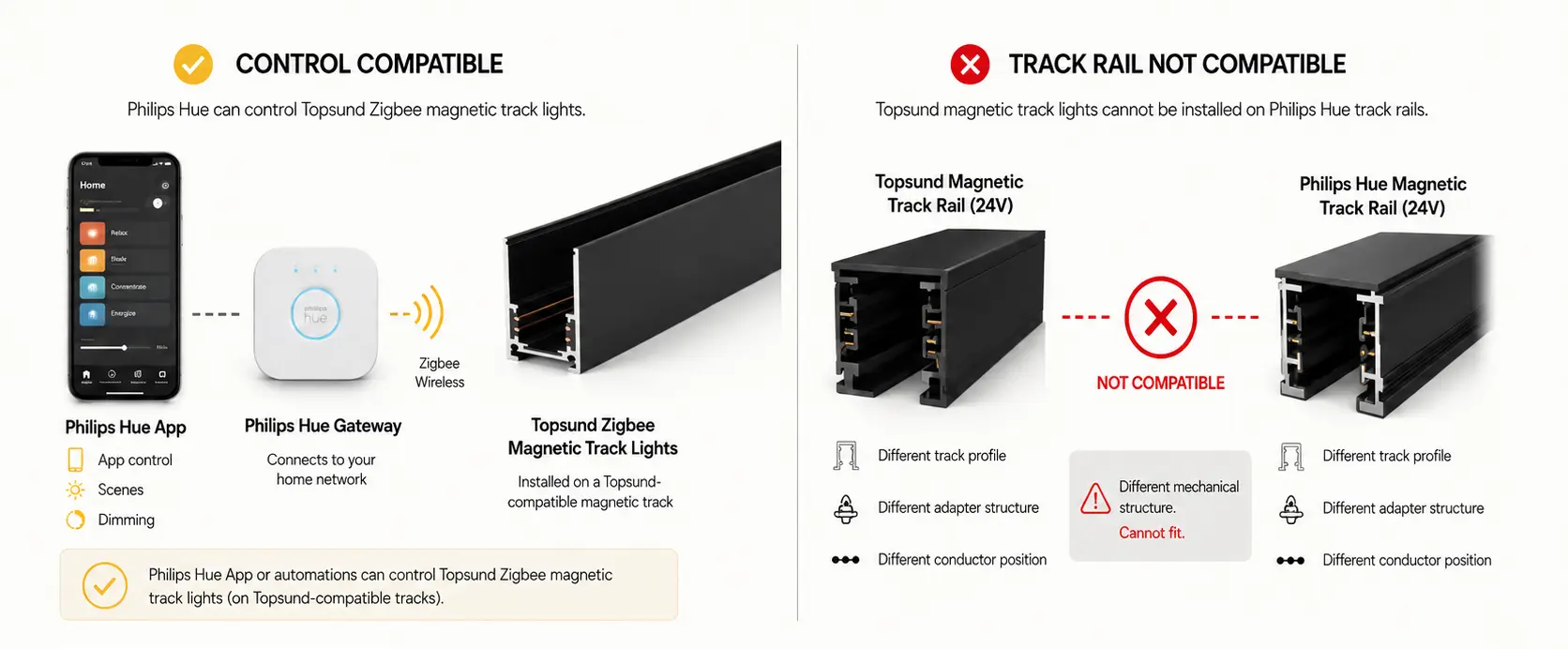
CONTROL COMPATIBILITY
Philips Hue Bridge → Selected compatible Topsund Zigbee 3.0 luminaires
Selected compatible Topsund Zigbee luminaires may be configured for control through Philips Hue Bridge, subject to the selected driver, pairing method and project setup.
MECHANICAL TRACK COMPATIBILITY
Philips Hue Track Rail × Topsund Magnetic Track Luminaires
Topsund magnetic track luminaires are not mechanically interchangeable with Philips Hue track rails because the systems use different track profiles, adapter structures, conductor arrangements and mechanical interfaces.
THE PRACTICAL MEANING
Control compatibility and track compatibility must always be checked separately. A compatible control ecosystem does not make the mechanical track platform interchangeable.
CONTROL ARCHITECTURE
Driver and Control Compatibility Must Be Checked Separately
Even when a luminaire is mechanically compatible with the track, the driver and control architecture must still match the intended project configuration.
COMPATIBILITY CHECK SEQUENCE
01 — Project Control Requirement
Define whether the project requires simple on/off, wired dimming, wireless lighting control or building-system integration.
02 — Luminaire Driver Version
Confirm that the selected luminaire uses the driver or control-module version required for the intended control route.
03 — Gateway / Interface
Where a gateway or interface is required, confirm the exact control architecture instead of assuming cross-system compatibility.
04 — Wiring & Power Architecture
Check 48V power, required control wiring, bus connections and circuit structure for the selected configuration.
05 — Commissioning & Validation
Confirm addressing, pairing, grouping, dimming, scenes or wall-control behaviour where applicable before project installation.
CONTROL ROUTES — WHAT MUST MATCH
01 — Non-Dim
Confirm the 48V power architecture, driver configuration, polarity where applicable and available power capacity.
02 — DALI-2
Confirm a DALI-compatible luminaire driver, the DALI bus architecture, required power and communication wiring, plus addressing and commissioning requirements.
03 — Casambi
Confirm the compatible Casambi driver or control module, required wireless control architecture and commissioning method for the selected luminaire configuration.
04 — Zigbee
Confirm a selected Zigbee-compatible luminaire or driver configuration, gateway, pairing method, groups, scenes, physical wall-control requirements and Tunable White support where applicable.
05 — KNX + DALI
Review the building-control and lighting-control layers separately: KNX building control → KNX-to-DALI integration → DALI lighting system.
COMPATIBILITY PRINCIPLE
The same track platform does not automatically mean every driver or control version can be mixed. Select the luminaire configuration according to the actual project control architecture.
PROJECT REVIEW
Confirm Compatibility Before Ordering
For replacement, extension or third-party track projects, compatibility should be reviewed before the final order or project installation rather than discovered on site.
01
Send Existing Track Information
Provide track photos, cross-section, internal dimensions, brand or model if known, existing luminaire and adapter photos, plus the installation method. If the brand is unknown, clear measurements become more important.
02
Confirm Mechanical & Electrical Interface
Review the track profile, adapter fit, locking method, conductor position, electrical contacts, voltage, polarity where applicable and power-feed arrangement.
03
Confirm Driver & Control
Define the required configuration — Non-Dim, DALI-2, Casambi, Zigbee or KNX + DALI — together with the gateway, wall control, dimming, grouping, scenes and Tunable White requirements where applicable.
04
Validate with Samples
Before a larger project order, validate the representative combination for mechanical fit, locking, electrical contact, power-up, dimming and pairing, grouping, scenes or physical controls where applicable.
PROJECT RECOMMENDATION
Validate Third-Party or Unidentified Track Systems with Representative Samples
Sample testing can confirm the tested combination’s mechanical fit, electrical contact, power-up and required control behaviour. It should support the project compatibility review, not replace a complete system specification.
TECHNICAL FAQ
Practical Questions About Magnetic Track Compatibility
Use these answers as an initial compatibility reference. Final confirmation should still be based on the actual track profile, adapter, electrical architecture, driver and control configuration.
COMPATIBILITY REVIEW
For an existing-track project, prepare clear track photos, dimensions, adapter details and available power or control information before requesting a review.
CHECK YOUR EXISTING SYSTEM
Not Sure Whether Your
Magnetic Track System Is Compatible?
Send us your track photos, dimensions, existing luminaire adapter and control requirements. We can review the mechanical, electrical, driver and control interfaces and advise what should be confirmed before samples or project quantities are ordered.